FAQs – Frequently Asked Questions
ATtiny13A Development PCB
Development / Breakout PCB for ATtiny13A MCU.
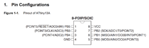
The ATtiny13A device can be programmed using ATMEL Studio 7 using C or Assembly code to control up to 5 I/O ports (see ATtiny13A data sheet for full details of the ATtiny13A pins and available functions – ADCs, PWM, etc…).
Note that nRST (RESET pin 1, PB5) should be programmed as INPUT, so programming interface can reset the ATtiny13A device during programming)!!
The ATtiny13 and ATtiny13A are the same MCU, but the ATtiny13A uses ‘pico power’ giving a low power MCU.
A programming device such as the ‘ATMEL JTAGICE3’ or ‘ATMEL ICE for AVR’ can be connected directly to ‘J8’ programming port via a 6-pin SPI programming header.
[1] QUESTION 1: Is shipping included in the price?
ANSWER: YES, FREE WORLD WIDE SHIPPING is included in the price.
[2] QUESTION 2: Is worldwide shipping available / included in the price?
ANSWER: YES, worldwide shipping is INCLUDED in the PRICE.
[3] QUESTION 3: Are the components shown on the PCB in photos shipped with the PCBs?
ANSWER: YES, all components are fitted – PCB is shipped as shown in photo below…
[4] QUESTION 4: Are batteries included?
ANSWER: NO, the PCB is normally powered from a PSU (power supply from 6.5V to 18V at 500mA). The PSU must be a DC (direct current) type supply, AC types do not work with the PCB.
[5] QUESTION 5: Is the PSU (power supply) included?
ANSWER: NO, the PCB is normally run from a PSU (power supply) from 6.5V to 18V at 500mA, but this is not included.
This voltage is converted to 5V on the PCB by ‘U1’ device.
The current and voltage of the PSU connected depends on the end user’s current requirements.
-
The green LED on the PCB draws around 20mA from the 5V rail generated on the PCB.
-
U1 will draw another 5mA or so.
-
The MCU current draw depends on code running, but should draw < 10mA (check ATtiny13A data sheet for exact figures).
So a 500mA+ PSU is recommended, based on current draw (amperage) requirements of your prototype.
The PSU must be a DC (direct current) type supply, AC types can not to be used with the PCB!!
[6] QUESTION 6: Will the PCB run from 5V or lower?
YES, the MCU can be powered directly using header connection ‘J1’, if component ‘R1’ is removed.
‘J1’ (normally a 5V output from ‘U1’) can be used to apply a 1.8V to 5V voltage, to run the MCU directly…
Note, with the PCB used in this mode, ‘R1’ must be removed to prevent damage to ‘U1’.
The green ‘Power OK’ LED (LED1) will still light for any voltage greater than around 3V applied at the ‘5V’ output (with ‘R1’ removed!!)
[7] QUESTION 7: With what logic levels is the PCB compatible?
Note the MCU (micro controller) will work at 5V logic levels.
If the user wants 3.3V levels from the MCU, ‘U1’ device (6.5V to 18V input, 5V output) can be swapped to a 3.3V output (SOT-223) type.
[8] QUESTION 8: How do you connect / program the PCB?
The PCB works from a 6.5V to 18V DC power input.
-
Positive input power voltage is applied at either pin of ‘J2’.
-
Ground input power voltage is applied at either pin of ‘J3’.
An SPI programming port is used to write software into the ATtiny13A MCU.
A programming device such as the ‘ATMEL JTAGICE3’ or ‘ATMEL ICE for AVR’ can be connected directly to ‘J8’ programming port via a 6-pin SPI programming header.